ConeCalc3D Help
ConeCalc3D is a
program to calculate the flat sheet metal pattern needed to construct
a cone of certain dimensions.
Regular Cones and Modified Cones Regular cones are your normal everyday cones with concentric top and bottom diameters with height and angle.A modified cone can have the top diameter shifted or angled. A modified cone is an Oblique Cone or Oval Cone. But on both kinds you will to fill in Regular cone data.
Enter
Cone Data You
only need one diameter and two other dimensions to define a cone.
Enter the ones you have available.


Filling
the cone dimensions
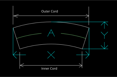
On the Enter
Data tab is a picture of an example finished cone shape. It is a cross
section view. It has the possible dimensions labeled.
Enter the
desired dimensions of the finished cone shape.
You only need to enter one diameter and two others of the five
possible dimensions of the final cone. The other dimensions will be
calculated from these.
- The
Bottom Diameter needs to be larger than the Top Diameter.
- Height
is the height of the cone. If material has a thickness use the
height from the inside corners or outside corners, but not both.
- Angle
is optional in case you don't have one
of the other dimensions.
- Length
is the length along the angle of the cone.
- Overlap
is optional. See below.
These dimensions are system agnostic, except when it comes to printing , so whether you enter the cone dimensions inches or millimeters, or anything else, the result will be in the same units..
To calculate the
result, click "Calculate" on the Main Menu, or Calculate button, or
press F2 function key.
Press F2 to Calculate cone. or Main Menu - Calculate. A 3D model of the calculated cone is displayed on the Cone tab. The Dimensions that you did not enter are filled in with blue color from the calculations. The model is interactive so you can change a dimension and press enter key and the model will change. You can hold down the left mouse button and drag the view of the cone around in the window

You will notice that this example the last two items in the Enter Cone Dimensions box are blue. The blue items were calculated from the other data that was given for your reference.
After
calculating, you can see the results on the Result
and the Sheet tabs.
On the Result
tab you will find the dimensions of the resulting flat pattern that
you would manufacture and later bend around
so the two straight edges meet. the result is a cone shape.
A drawing is
made in the window of the flat pattern shape with the dimensions
labeled.
Flat
Shape - On
the Flat Shape Tab is shown a drawing of the Flat Pattern and the
dimensions that are needed to make the flat pattern. Drawing in window
can be zoomed with mouse wheel and panned with center mouse button or
ctrl-left-mouse button.

Overlap
Normally, the flat pattern dimensions are are exact and don't have any extra material for overlapping the edges. If you want extra material on the edges of the cone then add here. Half the extra material is added to both edges. If you enter 0.5 for overlap the shape of the original will be produced on the screen with the addition of red lines offset from each edge by 0.25. The dimensions shown will be to the red lines of the extra material.
Segment Angle: In
case
you need a partial section of a cone, you can enter an angle in the
Segment Angle box. The angle is the angle on the finished cone. So an
angle of 180 would make a half cone, an angle of 90 would make a
quarter of the cone etc. This applies the new flat dimensions to the
screen and the printed flat pattern. This only operates on regular
cones.
Cord and Radius

Modified Cones
You can modify
the cones in several ways:
- Shift
the top. (shifting the top is the equivalent of shifting the bottom)
- Angle
of Top hole. (can be plus or minus)
- Angle
of Bottom hole
- Top
Ellipse short axis. The long axis is the Top Diameter.
- Bottom
Ellipse short axis. The long axis is the Top Diameter.
Sometimes you need a cone with an offset top hole or angled top or bottom. These cones are real cones but the flat pattern cannot be described by radial dimensions. In order to make these cones you would have to have a pattern that you could put on the material to draw the shape so you can cut it. That's where Printing the Flat pattern comes in below.
The Height dimension is always the height from the center of the bottom diameter to the center of the top diameter in the vertical direction.
Elliptical Cones: You can make a cone that has an ellipse on the top or bottom instead of a circle. These are the equivalent of a regular cone that has been squished into a oval or ellipse. The flat pattern has been compensated for the squished shape. When you assemble it, it will be a regular cone shape that you have to squish to your planned elliptical shape.This calculates a true ellipse from Diameter and Ellipse Short Axis. Diameter is the long axis.

Cylinders: You
can
make a cylinder when the Top Diameter and Bottom Diameter are the same
value. The Top and Bottom Short Axis also have to
be the same - otherwise its actually a cone. Of course, the flat
pattern for a cylinder is a rectangle. You can make a cylinder with a
Top Angle or Bottom Angle, but not with Top Shift. A Top Shift can be
duplicated with Top Angle and Bottom Angle.
Sheet
Optionally, you
can enter the size of a sheet of material for calculating how many
flat cone patterns will fit on it.
If you entered a
sheet size, there will be a drawing representation on the Sheet
tab.
You can zoom and
pan the drawing. Zoom in and out with the mouse wheel.
Control-Left-Mouse button, or Middle Mouse button will drag the
picture around.
The Zoom All button will bring you back to window size.

Enter
a value in
"Clearance Between"
if you want there to be a distance horizontal and for extra spacing
between the patterns on the sheet.
This only
applies to regular cones. With Modified cones the Sheet page is empty.
Saving and Loading
You can save the
cone dimensions you entered in case you want to use them again later.
Main Menu - File - Save Definition
You can load
those settings again with Main Menu - File - Load Definition
When the program ends, the current settings are saved to a .cone file. If a file name has not been chosen, the name will be "untitled.cone".
Printing
You can print
out a single sheet report that shows the cone dimensions entered, flat
pattern results, and drawings of the single and full sheet flat
patterns.
Main Menu - File - Print Data PDF
Printing Flat Pattern
Main Menu - File - Print Flat Pattern PDF
This creates a
multiple page PDF file that has a full scale
drawing of the flat pattern. This PDF can be printed on a printer on
multiple letter size sheets of paper. The sheets can be cut out for
use as a pattern for other material. Make sure you print the PDF file
to the printer with the setting "Actual Size".


There is a
printed border box around the edges of each page. Trimming these off
will make the printed pattern section line up with the next page. Cut
them out and tape them together to make one whole pattern. There is a
limit of about 30 pages in size.
For OSX users,
the PDF file may not display correctly in the built-in Mac previewer,
may need to install Adobe Acrobat Reader.
Saving drawing to CAD file
It is possible
to save the single shape and sheet flat patterns to a CAD file for
importing into another CAD program.
Save the flat
pattern of the cone from Main Menu - File - Save Flat Pattern CAD.
Save the sheet CAD with the button on the Sheet page.
File can be saved as DXF, CDL or IGS format. In Windows you can choose the file type from the drop-down list. In OSX it will save it according to what file extension you give it. Output unit is Inches.
Main Menu - File
- Save 3D CAD will save the wire-frame CAD of the 3D cone shape to a
DXF, CDL or IGS file.
Settings
Main Menu - File
- Settings will bring up Settings dialog.

Normally it doesn't matter what units you are using as long
as everything is the same. The only time the units is important is
when printing on the printer at 1:1 scale. The Units setting will
affect the printing of the Flat Pattern PDF.
If Load Last
File on Startup is checked, the last cone file you were working
on will be automatically loaded.
If Show Bend
Lines is checked, the Bend Lines box will show up. Changing the
value in the box (min of 4) will make lines on the flat pattern for
that number of segments.
If Show Seam
Line is checked, the Seam angle box will show up.
Seam Angle: When printing the flat pattern the seam is shown as starting at 0 degrees on the cone. If you wanted a pattern that started at a different angle you can put that angle into the Seam Angle box. This will draw a line on the pattern where that angle should be. After printing out the pattern you can manually cut the pattern along that line and then stick the other two ends together so that your pattern now starts and ends at the angle you want.

The Bounding
Box size displayed on the Seam Angle bar will give the overall
size of the modified flat pattern.
Seam Angle is
not shown when the shape is a Cylinder.
If Show Side Cuts is checked, the Side Cut box will show up. .

You can cut the cone by a width or a arc length.

This draws lines on the flat pattern that represent these edges:

PDF Page Size: The
PDF
page size can be set here. If you have a printer that can print large
poster size paper the PDF will be divided up into lesser number of
pages. The page size is embedded into the PDF file
so you need to set this the same as the paper size you are using.
The program
settings are saved in a file, "ConeCalc3D.ini" in the user documents
folder.
Square to Round
ConeCalc can also
make flat patterns for Square to Round transition pieces.

Choose the
Square tab to enter dimensions for square to round pattern.

Top Diameter: This is the
size of the hole on the top.
Bottom
Width:
The
bottom width, left to right. (X direction)
Bottom
Length:
The bottom size, front to back. If this is blank
then the bottom width will be used. (Y direction)
Height: Height from bottom
to center of top diameter.
Modifiers:
Bends
per corner:
Number of bend lines on each of the four corners. The top diameter has
(Number of bend lines * 4) steps. Must be between 4 and 10.
Top
X Shift:
Shifts the top diameter off the center in the X direction.
Top
Y shift:
Shifts the top diameter off the center in the Y direction.
Top
Angle:
Angles the top diameter direction on the Y axis.
Half
Pattern:
Check Box to create Half Pattern instead of Full Pattern.

The created flat pattern has the split side at right side face of the 3D model.The pattern can be printed like above, or the CAD file can be saved.
Activation
After installing
the trial version application, permanently activate it by the
instructions at https://i-logic.com/conecalc3d/activation.htm
Copyright © 2022 by i-Logic Software